User manual
Analyzer SOLO O2
version 2022/02/02
#8302
Content
Safety warning
01. About firmware and hardware versions
01.1 Hardware limitations
01.2. Upgrade to a helium analyzer
02. Measuring principle
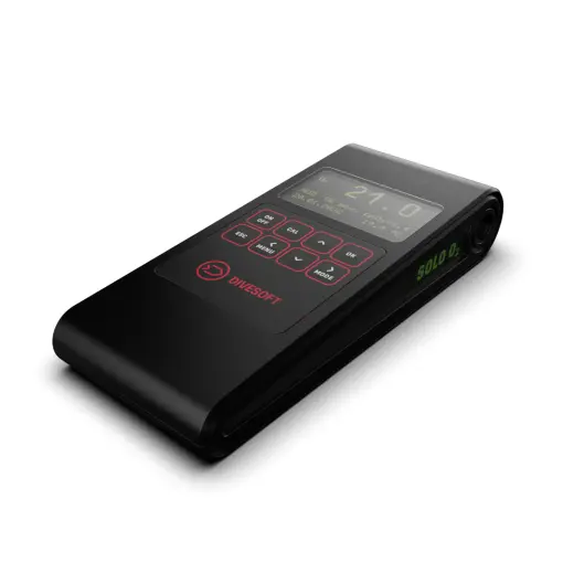
03. Description of the analyzer
04. Operating the analyzer
05. Measuring O2 concentration
06. Display modes
06.1 Calibration of the oxygen sensor
07. Other functions
07.1 Continuous analysis
07.2 Gas mixing solver
07.3 Gas mixing simulation
07.4 Ambient pressure
08. Special accessories
08.1 Flow regulator
09. Set-up
09.1 Preferences
09.2 Measurement units
09.3 Mixing of gases
09.4 Continual analysis
10. Charging and battery status
11. Maintenance
11.1 Battery replacement
11.2 Oxygen sensor replacement
11.3 Disassembly of the instrument
12. Connecting to a computer
13. Defects and removal thereof
13.1 Error messages
13.2 Instrument malfunctions
14. Technical data
Safety warning
This analyzer is designed for measuring the content of oxygen in an air-oxygen gas mixture.
This analyzer doesn’t contain helium sensors and IT IS NOT intended to measure helium mixtures such as Trimix, Heliox, Heliair or Triox.
It cannot be used to analyze mixtures containing other gases than those mentioned above
The physical and chemical principles of the sensors used do not guarantee that the sensors will be selectively sensitive to a specific gas (oxygen); there are a number of gases to which the sensors respond. Therefore, the gas composition shown by the analyzer does not mean by itself that the real composition of the mix is equal to the displayed values. The displayed mix composition is invalid unless the mixing technology ensures that there are no other gases present in the mix except air/nitrogen, and pure oxygen.
The analyzer is not a certified measuring instrument The results of measuring are only informative and it is not possible to use such results where a certified measuring instrument is required
When analyzing mixes in situations where the incorrect composition of the mixes could cause material damage, injury to health or threaten human health or life, for example in the case of breathing mixes for diving, the results of the analysis may not be used as confirmation of the correct mix composition In these cases, the analyzer can only be used as an aid for increasing the probability that such incorrect mix composition will be detected before its use. The correctness of the mix composition must be established by the technology used to prepare it.
The correct preparation of breathing mixes for diving (nitrox – oxygen-enriched air) requires special knowledge and experience which is possible to gain, for example, through an appropriate course. A failure to apply such knowledge can lead to an incorrect mix, even though the results of the analysis are seemingly correct Such a situation can also be the result of a failure to take into account the influence of temperature and compressibility, an insufficient blending of the mix and other factors.
Please remember that the analyzer can be broken or damaged and that the oxygen sensor is by its nature subject to ageing and thus its properties deteriorate.
Therefore always verify the measured data in another way, such as by precise preparation of the mix, another analytical method, etc. In addition, the measured value must be subject to critical assessment using a common-sense approach and if it differs from the allowable variation of mixing accuracy, it must be considered invalid.
01. About firmware and hardware versions
Analyzer SOLO O2 is equipped with a microprocessor whose program (firmware) is continuously updated. This manual is for firmware release 2.32, but the manual can be applied to any hardware or firmware version. Manual is primarily written for hardware version 3.1.
01.1. Hardware limitations
Analyzer SOLO O2 does not contain a helium sensor and is designed for air, nitrox and oxygen analysis only.
01.2 Upgrade to a helium analyzer
Analyzer SOLO O2 can be upgraded to a helium analyzer. During this upgrade, some hardware parts of the instrument are replaced and new firmware is uploaded.
For these reasons, the upgrade is only possible through a Divesoft service technician or directly at Divesoft. A list of Divesoft service locations can be found here: https://www.divesoft.com/en/contacts/service-points
02. Measuring principle
The described measuring principle is valid only for mixes of air, nitrox and oxygen.
An electrochemical sensor is used to determine the oxygen content. The voltage at the sensor’s output is proportional to the oxygen content in the analyzed mix The sensor has a limited service life and the proportionality of the dependence of voltage on the oxygen content changes over time; therefore, it has to be regularly calibrated It is possible to choose between single-point, two-point and three-point calibration. Single-point calibration is fast, especially if air is chosen as the calibrating mix. For greater accuracy of the measurement, two-point calibration is used with two different mixes, typically air and pure oxygen. For strongly hypoxic mixes, i.e. mixes containing less than approximately 15% oxygen, three-point calibration is recommended In this case, the third calibration gas should be a gas with zero oxygen content, i.e. pure helium or argon.
Gas is delivered to the analyzer from a sampler connected to the compressed-gas tank and the gas flow is controlled using a nozzle to provide the volume needed for the analysis.
03. Description of the analyzer
The lightweight and robust body is made from ABS-PC.
On the front side, the analyzer features a membrane keypad and an OLED display on which the measured values are shown.
Measured gas is fed into the analyzed-mix inlet on the back of the analyzer. From there, it enters the oxygen-sensor block and is expelled into the air by the mix exhaust. The rated flow of the analyzed mix is 0,2 - 0,4 L/min.
The analyzer is powered by a built-in battery, charging is possible through USB-C connector on the side of the analyzer.

04. Operating the analyzer
The analyzer is operated using the keys on its front panel.
It is activated by pressing the ON/OFF key for approximately one second. Upon activation, an automatic check of the instrument is performed and the analyzer automatically switches to the measuring mode.
When this key is pressed, the firmware version code and serial number of the analyzer are displayed. If you need to read this information, just hold the key down longer when activating the unit.
The analyzer is deactivated by pressing the | ON OFF | key for about one second again.
The | MENU | key displays the available options. The menu changes in individual measuring modes, depending on the functions relevant to the applicable mode.
The | OK | key is used to enter the selected menu item, confirm a changed value or perform the prepared action. The selected menu item can also be called up by repeatedly pressing the | MENU | key.
The | ESC | key is used to exit the menu or return from the value editing mode without saving the changed value.
The | ˄ | and | ˅ | keys are used to browse the menu or change the value of a number above the cursor.
The MODE key is used to change the display mode or to change the cursor position in the number editing mode.
Other functions of the keys are described in the relevant chapters.

05. Measuring O2 concentration
The plastic simple flow limiter is used in the basic configuration (see illustration).
Connect the simple flow limiter to the input port on the left side of the analyzer. Slowly and gradually open the cylinder valve so that the gas flows gently. Insert the Simple Flow Limiter into the bottle valve and press down so that the O-ring seals against the valve. Avoid letting a sharp gas surge directly into the analyzer. For better and more accurate results, use Divesoft's optional Professional Flow Limiter.

The analyzer switches into the oxygen measuring mode upon activation, so there is no need for you to set up anything. Open the valve on the bottle to let the gas flow in. The gas composition is displayed after approximately 5 – 10 seconds.
With the | OK | key, you can suspend and, by pressing it again, resume measuring. When measuring is suspended, the last measured values remain displayed. During measuring, the | ˄ | key can be used for temporarily increasing the brightness of the display to maximum (e.g. if the display is exposed to sunlight).
When the measuring is completed, close the valve on the tank. If you use Professional Flow Limiter discharge the excess pressure of the gas by loosening the discharge valve (generally 1/2 turn suffices) so that the flow limiter can be unscrewed from the tank valve.
Warning: Do not unscrew the discharge-valve spindle completely; a steel ball is contained inside which upon opening could be expelled and cause injury or be lost.
06. Display modes
Upon activation, the analyzer is normally in the O2 mode, in one of the two display formats
The basic format shows:
— The oxygen content in the mixture in perce
— MOD (mixture’s Maximum Operating Depth) at certain preset ppO2
— Preset ppO2 value
— The temperature at which the gas was measured
The well-arranged format shows the composition in a way used by divers to call the mixtures:
— Air: air with the oxygen content between 20.5 % and 21.5 %
— EAN, for instance EAN 36, is air enriched with oxygen, in this case up to 36 % oxygen
— Foul Air, for instance Foul Air (10 % O2), is foul or vitiated air with a reduced oxygen content It cannot be mixed with gases designed for preparation of breathing mixes commonly available to the diver (air, oxygen, helium); therefore, its presence indicates a problem. This may include ongoing corrosion inside the bottle or contamination of the mix with argon, carbon dioxide or another gas. Such air cannot be used for breathing under any circumstances.
In addition to the mix composition, this well-arranged format shows approximate values of the maximum operating depth (MOD).
MOD indicates the depth to which the diver can dive for a short time under otherwise ideal conditions. The limit of partial oxygen pressure equal to 16 kPa is used in the calculation, and seawater and the static pressure at sea level are taken into account. This reading is for orientation only, and for an actual dive it must be calculated using the data of the specific dive. The minimum pO2 can be set according to your own requirements: „/ Preferences / Partial pressure O2“
The following formula is used for the calculation:
Pmax	maximum allowable partial oxygen pressure, chosen as 160,000 Pa
P0	static pressure at sea level, 101,325 Pa
RO2	relative molar concentration of oxygen in the interval 0 to 1
ρ	seawater density, 1028 kg m−3
g	standard acceleration of gravity, 9.80665 m s−2
where:

Warning: The maximum operating depth (MOD) calculated for an actual dive is usually lower than the depth indicated by the analyzer.
Warning: To determine the MOD values, always use the procedures and formulas that you learned in specialized courses of diving with mixes. The values indicated by the analyzer are for orientation purposes only and are not sufficient for correct dive planning.
06.1 Calibration of the oxygen sensor
The oxygen sensor’s properties change over time and it is therefore necessary to recalibrate it. We recommend that such calibration be performed at least once a month The analyzer is equipped with built-in barometer sensor, which compensates for changes in altitude while traveling to dive sites.
Calibration of the sensor is performed as either single-point or two-point or three-point. During single-point calibration, the content of oxygen in air, which is known and constant (20.95 %), is measured by the sensor. The calibration constant of the sensor is set so that the instrument displays 21.0 % (after rounding).
Two-point calibration proceeds in the same manner as single-point calibration, but uses two calibration gases – pure oxygen and air. Two-point calibration is more arduous as it requires the use of oxygen. However, it provides more precise results during measuring.
Thee-point calibration is recommended for measuring hypoxic mixes, containing less than approximately 15 % oxygen. In this case, the third calibration gas should be a gas with zero oxygen content, i.e. pure helium or argon.
Calibration of the oxygen sensor is started by pressing the | CAL | key at any time during the measuring.
As the first step of calibration, we must choose between single-point, two-point or three-point calibration using the | ˄ | and | ˅ | keys and confirm the selection using the | OK | key.
It is then necessary to choose the oxygen content in the calibration mixture.
The oxygen content is adjusted by tenths of a percent by pressing the | ˄ | key (to increase the content) or the | ˅ | key (to decrease the content). Use the | MODE | key to choose whether to make adjustments by tenths, whole units, or units of ten percentage points. Upon setting the desired values, confirm the data using the | OK | key.
For quickly setting typical values when setting the oxygen content it is possible to use the | CAL | key, which sets the oxygen content at 21 % in the case of the first calibration point or 100 % at the second point and 0 % at the third point.
Upon setting and confirming the calibration of gases, calibration of the sensor begins. The current calibration point, sensor voltage in millivolts and the temperature of the gas appear on the display.
After the temperature and voltage have stabilized (however, at least after ten seconds), the STABLE prompt appears, which means that it is possible to confirm the performed calibration using the | OK | key. If the measured values change before the | OK | key is pressed, the STABLE sign disappears and calibration proceeds until further steady values are attained. If multi-point calibration is set up, then calibration according to the other gases proceeds similarly.
07. Other functions
07.1 Continuous analysis
The Menu/Continual Analysis option activates the function of continuous-filling monitoring. This mode makes it possible to set up the upper and lower limit of oxygen content. The analyzer continuously measures the concentration of these components and if the preset limits are exceeded, it makes a beeping sound. This mode is applied when the analyzer is used as a safety component during continuous nitrox filling, where a defect of the mixing apparatus could cause increased oxygen concentration potentially resulting in a fire or an explosion of the compressor.
In the mode for continuous filling, the limit values can be changed after pressing the | MODE | key.
07.2 Gas mixing solver
When the Menu/Gas mix solver option is selected, the gas-mixing solver function is activated. The solver computes the procedure for mixing the required gas mix of up to three gases. It can even include the remaining mix in the bottle to be filled in the calculation. The gases are displayed in the following order:
the remaining gas in the bottle,
added mix 1–2, the required mix.
For each mix, the composition, volume of the bottle (the actual, “water” volume of the bottle is specified) and gas pressure in the bottle are specified. If the volume of the gas is unlimited (for instance, if supplied by a compressor at a constant pressure), enter the bottle volume as zero. The mix composition may be entered either manually (after pressing the | CAL |, or the analyzer can be switched to the measuring mode by pressing the | OK | key and the relevant mix can be measured directly. After pressing the | CAL | key, edit the selected value by pressing | OK |. Then you can enter values | ˄ | and | ˅ | . Press | MENU | to move the cursor in the order. Confirm the selected value | OK |. After the data are entered, initiate the calculation using Menu/Solve (since it is first option, you can just press | MENU | key twice). The calculation may take up to one minute. Upon completion, results are displayed in one of the three possible forms, which can be switched between using the | ˃ | key (see the example).
Example
There is remaining air with the pressure of 120 bars in the twin bottles with the volume of 2 × 12 liters (total volume of 24 liters). The required mix is Nitrox 50 with the required pressure of 230 bars. You have fifty-liter distribution bottle containing oxygen, and a compressor with the output of 330 bars. Enter:
A:	Air		24L	120
1:	O2		50L	200
2:	Air			330

D:	50.0	24L	230
and start the calculation | MENU | | OK | . When the calculation is completed, the following data are displayed:
Disch.	to	71.9 bar
O2	to	156.4 bar
Air	to	200.0 bar
meaning that the twin should be discharged to the pressure of 71.9 bars, then oxygen added until the pressure of 156.4 bars is achieved and, finally, air added to reach 200 bars. When the MODE key is pressed, the same result is displayed; however, it is expressed in pressure to add or to discharge:
Disch.	-48.1 bar
Add	84.4 bar O2
Add	73.5 bar Air
or decrease the pressure by 48.1 bars, increase the pressure by 84.4 bars by adding oxygen, and 73.5 bars of air. The last mode is similar, but as it is designed for gravimetric filling (using a chemical balance), the amount of gas is specified in kilograms:
Disch.	-1.3707 kg
Add	2.6608 kg O2
Add	2.0970 kg Air
Please note that the solver takes into account the pressure drop in the gas charging bottles; therefore it does not try to recommend adding oxygen to reach 200 bars (which would be impossible anyway, given the limited oxygen supply); rather, it allows air to be partly discharged and oxygen is only added to reach the realistic 173.2 bars, with the rest of the air to be added by the compressor. At the same time, however, the solver saves the mix already contained in the bottle to the maximum possible extent; therefore, it does not let it discharge completely. Instead, only the necessary part of the mix is discharged.
07.3 Gas mixing simulation
Option Menu/Gas mix simulator is for Gas mix simulator function. Simulator will compute mixture content mixed up to from four gases. At every mixture is displayed composition and quantity of added gas in pressure units. You can enter mix composition manually (by pressing | CAL |) or switch to measurement mode by pressing | OK | and directly measure concrete mixture. Calculation of final mixture proceed continuously and mixture constitution is displayed on last row. Input values is the same as in the previous case.
07.4 Ambient pressure
Analyzer is equipped with a barometric pressure sensor. Thanks to this device can be calibrated for the atmospheric conditions and altitude. The atmospheric pressure and altitude can be displayed in the menu ambient pressure. Altitude is calculated from ambient pressure referenced to standard pressure at sea level (1013.25 hPa), depending on atmospheric conditions may differ from reality.
08. Special accessories
08.1 Flow regulator
For taking a gas sample for analysis, it is possible to use the flow regulator. It is used in a similar manner as the limiter. However, thanks to the use of a reduction valve, there is no decrease in flow and the measuring period is thus extended even with lower pressure in the tank. Its use is therefore suitable in filling stations and dive centers in which the content of half-empty tanks is checked.
The regulator is constructed from the Divesoft M12 modular system. The illustration shows only one of the possible configurations. Because the leads of the distribution block are equivalent, it is possible to freely reconfigure individual elements according to the user’s needs. Similarly, it is possible to replace the limiting nozzle with a reduction valve without the necessity of buying a full regulator assembly.
The regulator is connected similarly as the limiter. Besides the tank valve, it is possible to close off the gas output directly with the gas-output cut-off.
Warning: Over-tightening of the gas-output cut-off can damage or prematurely wear out the reduction-valve seat.

09. Set-up
09.1 Preferences
It is possible to change select properties of the analyzer in the basic mode (measuring of O2) in Menu/Preferences. Individual parameters have the following significance:
Brightness of the display in the scale of 1 to 127. The selection of low brightness (1) preserves the battery; the highest brightness (127) is suitable for use in strongly lit places. For temporarily increasing the display’s brightness, simply hold down the pressed | ˄ | key.
When activating the Backlight boost option, the brightness is automatically increased to maximum if the analyzer is powered with an external power-supply adapter.
Send data to USB determines the amount of data sent to the personal computer via the USB cable.
Partial pressure O2 is the maximum allowed partial pressure of oxygen used for calculating MOD
The Ref. temp. source option determines whether ambient temperature (Ambient) or defined temperature (Defined) entered in the following.
Ref. temperature parameter is used for calculating the estimated pressure in the tank (by using plug-in thermometer only).
9.2 Measurement units
Other settings are available in Menu/Measurement units Here the analyzer can be switched to metric mode (Metric units), imperial-units mode (U.S. units) or the display of individual units can be selected separately for individual values (temperature, depth, pressure, volume, mass). The unit settings do not affect the calculations (with the exception of final rounding), as the analyzer works in SI units internally.
Notice: Meters and feet are indicated as units of depth, though in reality this concerns hydrostatic pressure (pressure at the indicated depth in seawater).
9.3 Mixing of gases
The Menu/Gas mix solver - menu/Gas properties setting is available in the gas-mixing calculation and simulation modes Individual parameters have the following significance:
The State equation option is chosen if the mixing calculations will work with the ideal gas (the status equation PV=RT is used) or with the real gas (state equation according to Redlich and Kwong) The variant with the actual gas is more complicated in terms of calculation, and calculation can thus take a long time The ideal gas is sufficient for ordinary use
Ref. temperature is the temperature of the gas used for calculations
9.4 Continual analysis
Here the boundary values are set When these values are exceeded, an alarm is triggered: Alarm O2 low, Alarm O2 high.
10. Charging and battery status
At any time when the analyzer is turned on, you can check the battery status by pressing | ˅ | unless the key has other function at the particular screen. The value of the battery charge expresses double line at the bottom of display. Range is defined between 0 to 100%.
When the battery is close to discharged, connect the analyzer with provided cable to any USB charger or a computer USB port Full charge takes approximately three hours.
When the charger is connected, you can check the charging status by pressing | ˅ |. If the battery is not fully charged, the row of arrows is displayed on a scale from 0 to 100%. If it is already charged, a long double line is displayed.
All features of the analyzer are available during charging.
11. Maintenance
11.1. Battery replacement
The instrument uses a built-in rechargeable battery. Battery replacement is possible only in the factory.
11.2 Oxygen sensor replacement
The oxygen sensor has a limited service life. The analyzer automatically checks the sensor’s condition and, at the end of its life, the message “Oxygen sensor expired” is displayed upon activating the instrument. In this case the sensor should be replaced as soon as possible, as the accuracy of measuring the concentration of oxygen can no longer be guaranteed.
If you are not sure whether you are able to replace the sensor correctly, ask your supplier, vendor or service technician to change it.
To replace the sensor, first loosen the screw and remove the oxygen sensor cover.
Then disconnect the molex connector from the sensor, do not to pull on the wiring coming out of the instrument.
Unscrew the old sensor and install the new one in such a way that the o-ring on the sensor closely adheres to the analyzer. Do not use excessive strength to tight the sensor to avoid damaging the thread.
Reconnect the oxygen sensor connector, be sure to check the polarity. Finally replace the sensor cover.
Let the new sensor warm up before first calibration for at least 30 minutes after taking it out from the sealed packaging.
A no 1 Philips screwdriver is needed to replace the sensor.
After each sensor replacement, the instrument has to be recalibrated.

11.3 Disassembly of the instrument
Do NOT disassemble the instrument. Analyzer contains no user serviceable parts except the oxygen sensor.
Warning: Do not remove the printed circuit board from the analyzer. Replacing the circuit board requires a special procedure and calibration instrument.
12. Connecting to a computer
The analyzer can be connected to a computer using a USB cable.
Measured values are transferred to the PC via a virtual serial port. If you have not installed a suitable driver for the virtual serial port on the USB, use the free driver provided by the manufacturer of the USB chip used in the analyzer. This driver can be downloaded from the Internet at http://www.ftdichip.com/Drivers/VCP.htm. The specific driver can be selected from the VCP (virtual com port) category, depending on the PC and operating system used. Use the instructions attached with the driver to install it.
Data transfer must be activated in the analyzer, set Menu/Preferences/Send Data to USB to a non-zero value
Any terminal emulation utility can be used for data reception; for instance HyperTerminal is sufficient for Microsoft Windows. This utility is included in the basic Windows installation.
The measured data are transferred in the text mode. Every second, the analyzer transmits data in the following format:
O2 ooo.o % Ti ttt.t ~C pppp.p hPa YYYY/MM/DD hh:mm:ssCRLeg. „ O2 21.1 % Ti 23.9 ~C 1004.1 hPa 2021/12/20 12:03:00CRLF“
where:
ooo.o is oxygen content in percent,
ttt.t is temperature in farenheit or celsius,
pppp.p is barometric pressure,
YYYY/MM/DD hh:mm:ss is current date and time in 24h format,
CR is the ASCII carriage return symbol (decimal 13, hexadecimal 0D),
LF is the ASCII line feed symbol (decimal 10, hexadecimal 0A).
If there is an error in the measurement, the faulty entry is replaced with asterisks in the following form: **..
The output is in serial form in the format 8N1 (8 bits, no parity bit, one stopbit), speed 115200 bit/s, TTL level.
13. Defects and removal thereof
Upon activation, the analyzer is automatically tested to identify one of the following errors. All the error messages can be confirmed by the | OK | key and the instrument will continue to work; however in some circumstances in a limited operation mode.
13.1 Error messages
Error 2 Oxygen sensor damaged or missing
• The oxygen sensor is removed, disconnected or destroyed. The measuring of the oxygen concentration will be incorrect.
Error 3 Oxygen sensor expired
• The oxygen sensor is old and its output voltage is too low. The measuring will be inaccurate (the “Incorrect” warning is displayed next to the value of the O2 concentration) and some measuring modes cannot be activated. The sensor must be immediately replaced with a new one of the recommended type.
• This error may also occur if the instrument is filled with a hypoxic mix (a mix with low oxygen content) upon activation, for example immediately after previous measurement or if the measured hypoxic mix is delivered before the analyzer is activated. In such a case, switch off the instrument for a while, or connect it to a source of air before its activation. Never use your mouth to blow air in the inlet or the outlet of the analyzer to avoid vapor condensation inside the instrument (careful aspiration of gas by mouth is possible).
Error 4 Device is too cold
• The temperature of the analyzer is too low and the measuring may be inaccurate. Warm up the analyzer in a warm room to increase its temperature above the freezing point (5°C / 41°F).
Do not use a hot-air blower, air dryer, an oven or any other similar method to warm up the analyzer.
Error 5 Device is too warm
• The temperature of the analyzer is too high (for instance, if it was exposed to sunlight or stored in a car heated by sunlight); the measurement may be inaccurate. Cool down the analyzer below 40 degrees Celsius (104°F).
Warning Battery low
• The battery is almost empty, it has to be replaced or use the external power source.
13.2 Instrument malfunctions
• The instrument shows less than 0 % or more than 100 % of oxygen in the mixture. The displayed value arises directly from the measured and calculated value and has in no way been altered in the background. The possible measuring error is symmetrical and, for example, when measuring a mixture without any oxygen content, 0.5 % or −0.5 % oxygen can be displayed. Accordingly, when measuring pure oxygen, e.g. 99.5 % or 100.5 % can be displayed. If the deviation is within the measuring tolerance, this is not the result of a defect. In the case of a greater deviation, recalibrate the oxygen sensor. If the problem persists, replace the sensor.
14. Technical data
Dimensions: 85 × 205 × 40 mm (31/4 × 77/8 × 11/2 inches)
Weight: 332 g (without packaging and accessories)
Oxygen concentration measurement range: 0 to 100%
Operating pressure: 700–1100 millibars (20– 32 inches Hg), which corresponds to a standard atmosphere at 0 to 3000 m (0–10000 ft)
Mixture Pressure: Corresponds to an ambient pressure in the range of 700–1100 millibars (20– 32 inches Hg), which corresponds to a standard atmosphere at 0 to 3000 m (0–10000 ft)
Nominal gas flow rate: 0.2 l / min
Measuring cycle: 200ms
The connection dimensions of the sampler: Standard for a DIN valve (EN 144-2) for 200/300 bars (G 5/8 thread). Samplers with a connection to any standardized or common valves are available on request or as optional equipment
Oxygen sensor: R22 S (Molex connector)
Easy to replace O2 sensor
Oxygen sensor life expectancy: 2 years
Replaceable battery: Through authorized service center
Battery: 210 measurements or 7 hours of continuous operation
Battery capacity: 3,7 Wh
Warranty: 24 months, 12 months on battery and oxygen sensor
Charging and programming: USB-C
Charging time: 3–4 h
Display: OLED
Body: ABS-PC
ANALYZER SOLO O2 - USER MANUAL
Date of issue: 02 February 2022
HW 3.0, FW 2.29
Authors: Jakub Šimánek, Aleš Procháska
Published by Divesoft s. r. o.