CCR Liberty Heavy
User manual
Content
1.1 Responsibility of the Liberty Heavy user
2.3 Update of printed documentation
5.2 Fixing the canister with the head
5.3 Hose routing 2×3 litre version
5.4 Hose routing 2×7 litre version
5.4.1 Right post diluent first stage
5.4.2 Left post diluent first stage
5.5 Personal customisation of the position
5.6 Adjusting the counterlung position
5.8 Location of tanks for dry suit
5.9 Location of additional equipment
Introduction
1. Use of this manual
This is the Liberty Heavy rebreather manual.The manual only deals with the specifics of the Heavy version of Liberty and is only a manual supplementing the basic functions and controls described in the Liberty main manual. Operation of bailout rebreather mode features is described in the stand-alone Bailout standby mode manual.
To understand the full functionality of the device, read the CCR Liberty main manual.
The Liberty Heavy is intended for use exclusively by a trained person who is capable of fully understanding the instructions contained in this manual or is in the process of training with the Liberty Heavy in a course accredited by the manufacturer.
1.1 Responsibility of the Liberty Heavy use
Strong emphasis was placed on reliability during the development of the CCR Liberty Heavy. Individual internal parts are separated in order to minimize the impact that failure of a given part may have on the rebreather’s basic functionality. A number of systems have multiple backups. The logic of the Liberty Heavy’s control never prohibits the start of a dive even in the event that malfunctions are detected; it only indicates the status if able to do so in light of the damage. When cave diving, the inability to submerge can mean not being able to return from a dive; therefore, the Liberty Heavy does not impede submersion.
The user must always decide responsibly whether he/she switches to a backup apparatus or even starts a dive with a partially malfunctioning rebreather.
A Liberty Heavy user must accept the fact that diving involves risk. Following everything that the user has learned in the Liberty Heavy’s technical documentation and in training on diving with this rebreather can reduce the risk but cannot eliminate it. Safety when diving is further improved by regular training, methodical education and following good diving practices. Diving with a rebreather requires a far higher degree of carefulness and discipline than diving with an open-circuit apparatus.
If you do not accept the risk and you are not a trained, careful and disciplined diver, do not dive with the Liberty Heavy.
The manufacturer does not bear any responsibility for use of the Liberty Heavy if the apparatus has been modified in any way that is not stated in this manual or in the technical guidelines issued by the manufacturer.
The principle of a rebreather involves in recycling the breathing mixture. Carbon dioxide is removed from the exhaled mixture and is again prepared for the next inhalation after being replenished with oxygen. The composition of the breathing mixture changes continuously.
1.2 Notice
The Liberty Heavy is not a buoyancy compensator, nor a harness for attaching the device to the diver’s body.
2. System of documentation
2.1 Version
The technical documentation is subjected to a process of continual development and improvement.Therefore, please regularly check the website at www.CCRLiberty.com for updates.
2.2 Technical guidelines
The manufacturer can issue technical guidelines. It is strongly recommended that the user regularly checks www.CCRLiberty.com for new guidelines. Registered users will receive notifications by e-mail.
2.3 Update of printed documentation
The electronic form of the manual is always available in its complete, updated form.
The electronic and printed forms of the manual may not be completely identical. In case of insignificant changes (correction of minor typing errors, for example), only the electronic version is updated
2.4 User support
Registered users are entitled to technical support. The extent of free support can be limited.
The technical support department at Liberty systems s.r.o. will provide limited support for potential and unregistered users.Prior to submitting a question, please familiarize yourself with the general principles of rebreather diving with trimix and the freely available CCR Liberty technical documentation.
2.5 Use
Heavy Liberty Rebreather is a modification of the original Liberty Rebreather. Liberty Heavy retains the complete head of the device including electronics, handsets and all sensors. However, Liberty Heavy requires a different mounting than the classic Liberty. This procedure is included in this manual and assembly checklist
3. Description
Liberty Heavy can be used in a number of different configurations consisting of mutually compatible parts.The device’s own configuration can be created in the online configurator https://ccrliberty.com/configurator.
Liberty Heavy brings a new configuration of the popular rebreather with completely redundant electronics. Divers can clamp the Liberty to their own standard backplate, bringing a high level of comfort, versatility, and a wide range of height adjustment options for any diver’s body height. This gives the diver ample headroom that does not restrict anything. The adjustability of the device’s seating on the back brings the possibilities of fine-tuning the perfect trim.
The Liberty Heavy configuration has a 20 l wing in the base, but any other rebreather wing (with holes for hose passages) can be used according to the required volume to your chosen size and number of cylinders.
The Liberty Heavy allows you to change the configuration of the on-board cylinders from the classic 2–3 liter to the large 7 liter cylinders in DIR configuration. Up to 4 cylinders can be mounted in various combinations.
The removable wire stand allows very practical and convenient mounting of the off-board bottles while guaranteeing high stability of the device on land or on the boat.
The stainless steel frame of the instrument is well adapted for easy and elegant hose routing.
The Liberty Heavy is thus an excellent choice for all divers looking for a very comfortable, compact and stable unit with a wide range of customization options, for divers looking for a unit for the most demanding dives with many bailout cylinders, but also for recreational divers at the beginning of their rebreather career.
All the extremely advanced features of the CCR Liberty remain. The configuration uses the original back-mounted counterlungs and manual valve system right at the mouthpiece. The work of breathing thus remains unchanged from the highest standard Liberty rebreathers.
3.1 Conversion
Liberty Heavy is compatible with the standard CCR Liberty , so it’s possible to convert CCR Liberty to Liberty Heavy using a conversion kit.
The head including the handset and the buddy display, canister and scrubber are used from the back-mounted device.Alternatively, it is possible to replace the scrubber with a canister for a shortened version.This version is not a standard part of the conversion kit, and needs to be requested separately.
By purchasing the conversion kit to the back unit, Liberty Heavy can be rebuilt to classic CCR Liberty.
4. Assembly
WARNING: ALWAYS USE THE OFFICIAL CHECKLIST OR DIVESOFT.APP TO BUILD LIBERTY HEAVY

Checklists for CCR Liberty in .pdf format are available at https://www.divesoft.com/en/products/ccr-liberty/documents
4.1. Canister preparation
Since the Liberty Heavy has a different system of attaching the canister and head to the frame and backplate, it is imperative to always connect the head and canister with a clip.
WARNING: FAILURE TO USE THE BUCKLE WILL RESULT IN SEPARATION OF THE HEAD FROM THE CANISTER DURING THE DIVE, CATASTROPHIC FLOODING OF THE BREATHING LOOP AND RISK OF SERIOUS INJURY OR DEATH.
TIP: If using the canister only with the Heavy or in combination with the Liberty Light, always leave the clip on the canister and do not remove it. This will avoid the embarrassment of forgetting to install the clip before a dive or losing it.

Step 1
Open all the levers on the buckle and insert the tooth of the buckle into the lock on the scrubber canister
Step 2
Secure the buckle position on the canister with the buckle locking levers
Step 3
Insert the beak of the buckle into the head lock and secure with the main buckle lever. The closed buckle on the canister and head looks like this. All levers of the buckle are snapped, the buckle is firmly attached to the head and canister and there is no gap between the head and canister
To open the head again, first release the lock from both sides at the same time. Tilt the main lever to the maximum position to separate the head from the canister.
The Liberty Heavy system is based on a frame that carries both the bottles and the canister. The frame is always the same for all versions of Liberty Heavy. The only difference between the configurations is the placement of the two types of brackets on the frame.
For the 2–3 liter bottle configuration we use the small brackets. If we want to use the socalled GUE configuration with 7 liter bottles, we use large brackets. In both cases, it is still possible to attach a second set of bottles via the additional holes for the attachment straps.
Stand for 2×3 litre configuration. Stand for 2×7 configurationEach configuration comes with just one set of brackets suitable for that configuration. In case of combining different configurations, it is possible to purchase separately brackets for the given configuration.

5. Assembly
The Liberty Heavy frame is designed so that any wing and backplate can be used as long as they have standard bolt hole spacing. Assemble the Liberty Heavy by installing the wing, counterlung assembly and backplate onto the bolts in the frame one at a time. TIP: To make it easier to mount the wing and other components to the frame, it is a good idea to secure the bolt with red ring (included) so that the bolts do not come out of the frame during assembly of other parts.
5.1 Fixing the Tanks
Attach the tanks to the frame using straps with an buckle. The height of the tanks affects the reach of the low pressure hoses, so choose a height that will allow the hoses to reach the intended position. In particular, the position of the oxygen hose connection to the solenoid is critical Close the strap with the buckle and make sure the tanks are secured tightly enough. Insert the remaining end of the strap into the elastic loops on the strap so that it does not float.
5.2 Fixing the canister with the head
The head canister MUST BE PRE-ARRANGED WITH THE CHAIN as stated above. Stand the canister on the unit stand and screw the oxygen connection to the solenoid. It is imperative that this step precedes the attachment of the canister, as with the canister attached, fingers can no longer reach the oxygen connection.
SECURE THE CANISTER WITH THE CENTRAL STRAP
5.3 Hose routing 2×3 litre version
Two 3l tanks are mounted in the unit with the valves down. Diluent on the left, oxygen on the right. Both tanks have classic Nautec rebreather valves and are fitted with APEKS DST first stages with technical connections. The first stages are rotated horizontally and the technical connections face the diver. The three-hole side faces upwards.
5.3.1 Diluent routing
The three upper ports have hoses in order from left to right 1. BOV+DIL MAV; 2. ADV; 3. Inflator.
• H HP hose runs upwards along the frame attached with velcro straps on the side of the tank, then passes through a hole in the handle over the diver’s shoulder and the gauge is attached to the chest D-ring or under the rubber
• The BOV hose is routed in front of the frame (between the frame and the backplate) and is secured with velcro straps). It does not pass through the wing but makes an arc over the top of the wing and is routed along the inspiratory hose
• The ADV hose follows the same route as the BOV hose
• It is routed through the front of the frame. On the wing it runs from the inflator elbow along the inflator hose
5.3.2 Oxygen routing
There are two hoses leading out of the three upper LP ports. The middle port is for the solenoid hose, the outermost port is for the oxygen MAV.
• The BOV is routed in front of the frame (between the frame and the backplate) and is held in place with velcro straps). It does not pass through the wing, but makes an arc over the top of the wing and is routed along the exhaust hose.
• Solenoid hose – runs directly along the canister to the banjo.
A safety lock prevents the OPV from accidentally falling out. To remove the valve push it in to unlock, and rotate in the direction of the arrows. Indicated on the valve.
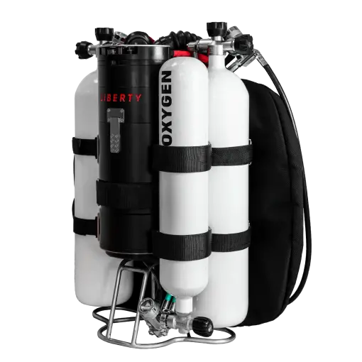
5.4 Hose routing 2×7 litre version
Two 7 litre diluent tanks are clamped in the frame with valves upwards, connected to each other by a flexible manifold. The two first stages of the Apeks DST are fitted with technical connections, and are positioned vertically, connections downwards.
5.4.1 Right post diluent first stage
• The high-pressure hose from the pressure gauge runs crosswise behind the head to the left side of the diver, where it is clamped into the D-ring on the belt.
• The 350 mm long ADV hose runs crosswise under the exhalation hose to the ADV T-piece.
• The 665 mm long inflator hose runs crosswise under both corrugated hoses to the inflator hose on the left.
• The long hose runs straight down from the bottom port. Second stage is not included.
5.4.2 Left post diluent first stage
• 580 mm long hose for MAV diluent, which runs along the inspiratory hose to the single hose adapter on the BOV.
• Dry suit hose leading directly down from the bottom port. This hose is not supplied with the unit.
5.4.3 Oxygen routing
The oxygen first stage is located on a 3 litre tank turned valve down and attached to the right oxygen tank so that the first stage extends below the scrubber canister. The oxygen first stage is also fitted with a technical connection.
• A 560 mm long solenoid hose runs from the technical connection then is routed along the right side of the frame through two velcro loops and then directly into the solenoid connection.
• The hose to the O2 MAV runs on the opposite side of the same part of the frame as the solenoid hose (on the tank side) and turns along the wrap hose to the O2 MAV at the wrap hose
• HP hose to gauge of standard length as on BMCL runs forward of the frame (attached between frame and backplate with velcro straps and exits on the left side where the oxygen gauge is connected to the diluent gauge and attached together with the diluent gauge
5.5 Personal customisation of the position
Each unit can be personally customised by positioning the backplate against the frame. Three holes in the frame and stand are used for this purpose. The higher you position the backplate, the lower the unit will be positioned on the diver’s body.
TIP: people with a shorter stature may have difficulty when the unit obstructs behind their head in the standard setup. In this case, it is possible to fix a screw to the top hole. This will move the unit down a few inches and give the diver a proctor behind the head.
TIP: people with tall stature may have difficulty with low counterlung seating at the default setting. This can result in impaired work of breathing. Moving the unit one hole lower will move the unit up overall and this will get the counterlungs in the correct position.
5.6 Adjusting the counterlung position
The poor position of the counterlung relative to the lungs fundamentally affects the work of breathing. The central part of the counterlung is provided with two pairs of holes for the passage of the screw. This allows the counterlungs to be positioned one level higher or lower.
5.7 Adjusting the trim
At Divesoft, we have tried to make the unit as balanced as possible. Yet, of course, it cannot be guaranteed that the trim will be tuned for everyone. Fine adjustment of the horizontal balance is achieved by moving the on-board cylinders relative to the unit. By not anchoring the first stages of the regulators, the diver has the ability to adjust the position of the cylinders to some extent. If this is not sufficient, additional weight can be placed on the shoulder straps or bottles using special pockets. These pockets are not included with the Liberty Heavy.
5.8 Location of tanks for dry suit
The dry suit filling tank can be positioned in two ways:
The standard way on the backplate. In this position, the tank may interfere with proper counterlung filling and thus impair work of breathing.
By placing it as a second set of cylinders. For this option, use the additional straps in the brackets. This Mounting can be used in both 2x3 liter and 2x7 liter configurations. You can also mount an additional bottle to inflate the BCD on the opposite side of the unit in the same way. This can save the amount of diluent used primarily for the important dilution of the loop with optimal and often expensive gas.
Straps for attaching the second set of tanks must be purchased separately
5.9 Location of additional equipment
The positioning of the light canister or heating system can be either classically on the belt, or if you have space left, the battery can be placed in the position of the second set of cylinders.
5.10 Assembly of the loop and Dive checks
USE THE MAIN LIBERTY USER MANUAL FOR THE REST OF THE REBREATHER INSTALLATION.
6. Maintenance
After each dive in salty or polluted water, the device must be washed with clean, fresh water. After each day of diving, disassemble the device. For dismantling, use the reverse assembly procedure.
Put caps on the MAV and ADV connectors and disinfect the entire loop, including the counterlungs, and rinse with drinking water. Let it dry in a shady, well-ventilated place. Treat the head of the device as shown in the main manual.
After diving in fresh water, it is not necessary to separate the backplate from the frame and stand, and it is possible to keep the wing and the center section of the counterlung. However, the counterlungs themselves must always be rinsed and cleaned and disinfected after a day of diving as above.
Do not expose the device to excessive sunlight or extreme temperatures
6.1 Storage
Store the unit thoroughly cleaned, disinfected and above all perfectly dried at temperatures between 4° and 25°C in a dry room. Prevent unwanted objects and animals from entering the instrument.
Protect oxygen and helium sensors from frost and moisture.
Refer to the basic Liberty user manual for details on maintaining the entire device.
LIBERTY HEAVY USER MANUAL
Date of issue: 1 . 9 . 2021
Author: Jakub Šimánek
Published by Divesoft s .r .o .
www .divesoft .com